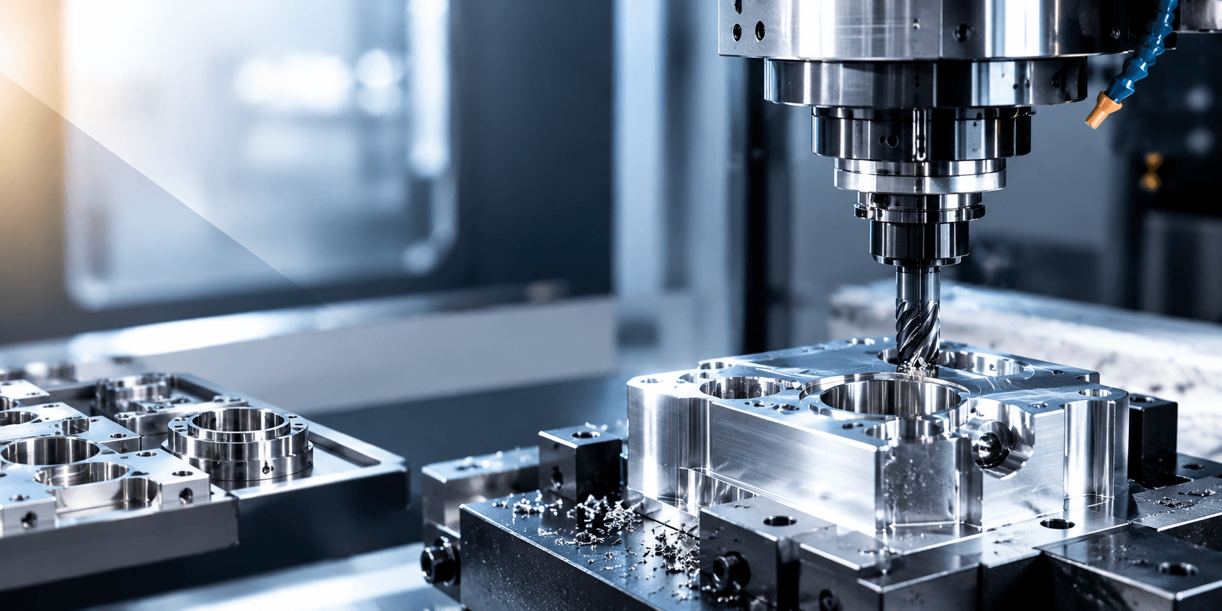
From precision-machined components to customised tooling and turnkey equipment solutions, Flexi Versa Group combines CNC machining, component fabrication, electro-mechanical assembly and turnkey machine integration to support demanding industrial and semiconductor applications.
Precision Engineering. Integrated Manufacturing Solutions.

Precision Engineering
Engineering excellence in every component
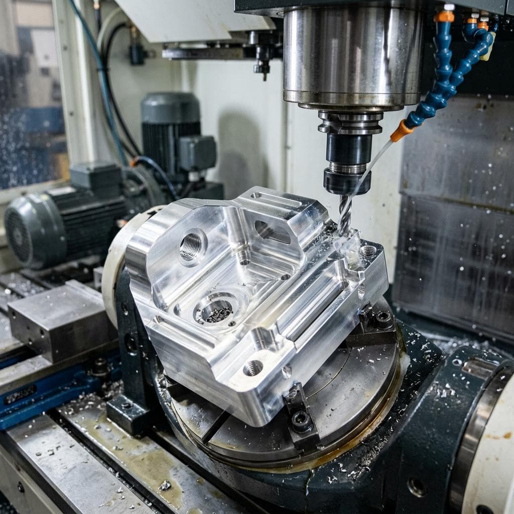
We work with customers to translate engineering drawings and specifications into precision-manufactured components, specialised tooling and integrated equipment solutions — supported by engineering collaboration, machining expertise, quality assurance and integrated manufacturing capabilities that carry a project from individual parts to complete equipment assembly.
Our Precision Engineering Capabilities
Engineering expertise for complex manufacturing requirements
CNC Machining & Large-Format Machining
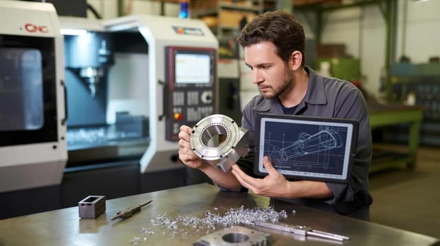
We provide customised CNC machining for precision-engineered components and larger machined parts used in industrial and semiconductor equipment. Our machining capabilities include 3-axis and 3+2-axis machining centres, supporting components with varying geometries and manufacturing requirements.
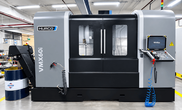
Precision Engineering Parts Fabrication
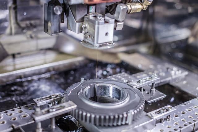
Jigs, Fixtures & Specialised Tooling
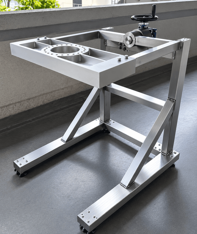
Turnkey Machine Design & Assembly
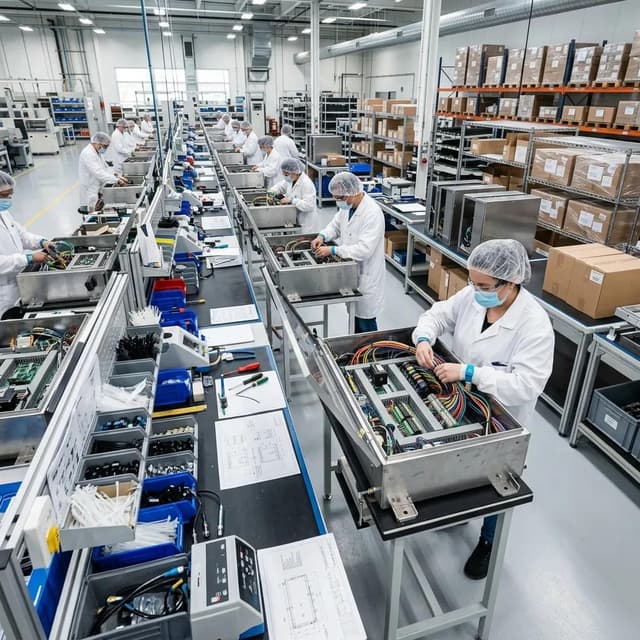
Electro-Mechanical & Cleanroom Sub-Assembly
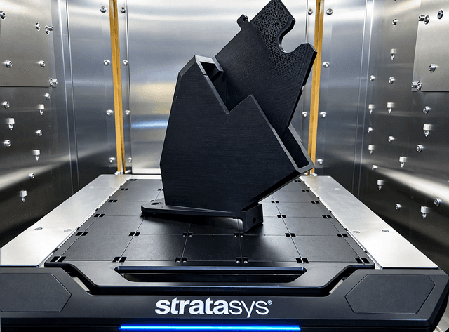
3D Printing & Engineering Prototyping
Engineering Collaboration & Design Support
From design to production, in one engineering workflow
At FVG, we work with customers during product development and manufacturing planning, supporting the transition from engineering designs to fabricated components and assembled equipment — including CAD/CAM programming, customer drawing review, custom fabrication and turnkey project coordination. Engineering files are supported in IGES, STEP, DWG, DXF and UG formats. Working with customer engineering drawings and design files. Customised component and tooling fabrication. Turnkey project coordination, component sourcing and assembly. We support engineering files in IGES, STEP, DWG, DXF and UG formats, as identified in our manufacturing presentation.
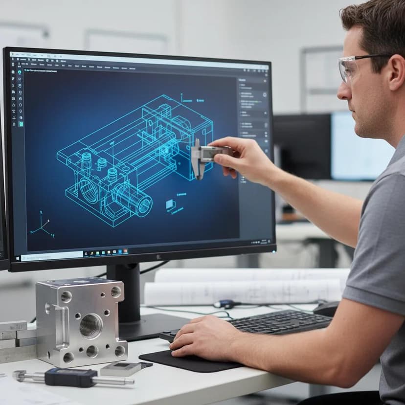
Engineering & Requirements Review
Understanding customer drawings, specifications, and project requirements is the foundational engineering step that turns a design intent into a manufacturable, inspectable, and repeatable production plan. It begins with a structured review of the drawing pack and associated documents: confirming the correct revision, part name/number, units, material grade and condition, heat‑treatment or coating callouts, GD&T datums, critical dimensions and tolerances, surface‑finish requirements, and any special processes (e.g., passivation, anodizing, plating) or testing/inspection needs.
Beyond the literal dimensions, skilled manufacturers probe the application context—what the part must do, what it mates with, and the operating environment—so they can distinguish truly critical features from those that can be relaxed to improve cost and lead time without affecting function. This understanding then drives process planning (choice of CNC machines, fixtures, cutting strategies), tolerance and capability analysis, inspection planning (which features to measure, with what tools and frequency), and clear communication back to the customer to resolve ambiguities, align on quality expectations (functional vs cosmetic), and lock in scope, timeline, and documentation requirements before any material is cut.
Machining & Component Fabrication
Manufacturing customised machined parts and fabricating required components is the core production workflow that converts approved drawings and specifications into physical, inspection‑ready parts tailored to a specific application. It begins with process planning and CAM programming: engineers translate the customer’s CAD model and 2D drawing into machining strategies, selecting datums, fixturing methods, cutting tools, and toolpaths, then generating G‑code that drives CNC mills, lathes (including Swiss‑type), and multi‑axis machines to remove material from raw stock in a controlled, repeatable way.
Raw material—metal or plastic bar, plate, tube, or forging—is prepared, fixtured, and machined through roughing and finishing operations (milling, turning, drilling, threading, boring, etc.), often in multiple setups or on 3‑ to 5‑axis systems to access complex features while maintaining tight tolerances and surface finishes. Where needed, fabrication steps such as welding, sheet‑metal forming, or assembly are integrated to produce complete subassemblies rather than isolated parts. After machining, components undergo deburring, cleaning, and any specified post‑processing (heat treatment, plating, anodizing, passivation, coating), followed by dimensional and functional inspection against the drawing’s GD&T, tolerance, and finish requirements before final approval and shipment.
Component Sourcing
Sourcing standard components according to project specifications and performance requirements is the disciplined process of selecting off‑the‑shelf mechanical, electrical, pneumatic, and hydraulic parts that satisfy the design’s functional, environmental, and regulatory constraints while supporting reliable, cost‑effective assembly and long‑term maintenance. It starts by translating the bill of materials and design intent into precise technical criteria for each item—load and torque capacity, speed and duty cycle, pressure and flow ratings, temperature and chemical exposure, vibration and shock levels, dimensional envelopes, mounting interfaces, and any safety or certification needs (e.g., CE, UL, ATEX)—then mapping those criteria to catalog parts from qualified OEMs and distributors.
Suppliers are evaluated not only on unit price but on lead time, availability, documentation (material certs, test reports), compatibility with existing systems, and lifecycle considerations such as obsolescence risk and ease of replacement, with preferences for standardized families that reduce part variety and simplify future MRO. The outcome is a vetted component list—bearings, fasteners, linear guides, motors, drives, sensors, valves, fittings, seals, etc.—that fits physically within the assembly, meets or exceeds the required performance margins, aligns with project timelines and budget, and can be consistently procured over the equipment’s service life.
Assembly & Integration
Assembling mechanical and electro‑mechanical equipment according to approved drawings is the controlled integration of machined parts, standard components, wiring, and subsystems into functional units that match the design intent and pass defined tests. Technicians start by reviewing the latest approved assembly drawings, schematics, wiring diagrams, and work instructions to confirm part numbers, revisions, fastener specs, torque values, lubrication points, cable routes, and test requirements, then kitting and verifying all components against the bill of materials.
Mechanical assembly proceeds by aligning and fitting subassemblies—frames, guides, bearings, shafts, actuators, and mechanisms—using precision measuring tools, fixtures, and alignment aids to achieve specified clearances, runout, and geometric relationships, while applying correct threadlockers, lubricants, and torque settings. Electro‑mechanical integration adds routing and termination of harnesses, connection of motors, drives, sensors, and controllers, and, where required, soldering or crimping in line with ESD and safety practices, followed by continuity checks and basic electrical verification. Completed assemblies are then functionally tested against the drawing and specification—checking motion profiles, interlocks, pressures, temperatures, and performance parameters—with any adjustments documented and final inspection records completed before release or shipment.
Inspection & Quality Assurance
Verifying components and assemblies against defined requirements using appropriate inspection equipment is the systematic quality‑control process that confirms every part and built‑up unit conforms to the engineering drawing, specifications, and performance criteria before release. It starts by establishing inspection criteria from the drawing and customer specs—identifying critical‑to‑function dimensions, GD&T controls (datums, position, profile, runout), surface‑finish calls, material and heat‑treat requirements, and any functional or safety tests—then selecting suitable measurement methods and tools for each characteristic.
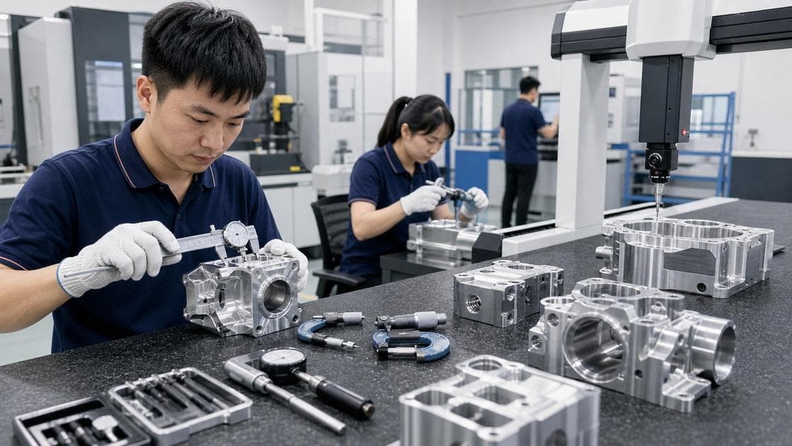
Dimensional verification is performed with a calibrated metrology suite: hand tools (calipers, micrometers, height gauges, dial indicators, bore gauges) for routine checks; optical comparators and vision systems for 2D profiles and small features; and coordinate measuring machines (CMM) or 3D scanners for complex geometry, true‑position, and profile tolerances, often programmed directly from the CAD model.
Industries We Serve
Supporting industrial & semiconductor applications
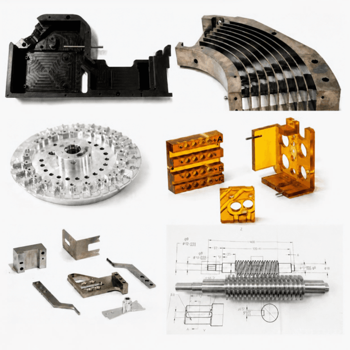
Semiconductor Equipment
Precision machining for semiconductor equipment encompasses the design and manufacture of ultra‑high‑accuracy mechanical components, specialised tooling, and integrated subassemblies that form the backbone of wafer‑fab and packaging machinery rather than the chips themselves. This discipline delivers critical parts such as wafer chucks, process chamber liners, showerheads, vacuum manifolds, precision stages, and metrology fixtures, all machined to tight tolerances (often around ±0.01 mm or better), with stringent surface‑finish, flatness, and cleanliness requirements to survive harsh environments like vacuum, plasma, high temperature, and corrosive gases while minimizing particle generation.
Specialised tooling extends this capability into application‑specific hardware—custom gas injectors, robot end‑effectors, reticle carriers, calibration mounts, and test sockets—engineered and qualified for particular processes, measurements, or handling tasks. Increasingly, suppliers also provide equipment assembly services, integrating machined components with sheet‑metal structures, motion systems, sensors, and cable harnesses in cleanrooms to deliver fully tested modules such as process chambers, wafer handlers, or metrology heads, thereby reducing handoffs, improving alignment control, and accelerating the path from prototype to production for semiconductor equipment OEMs.
Industrial Automation
Industrial Automation, in the context of precision machining, refers to the end‑to‑end provision of customised mechanical parts, fixtures, and equipment‑related engineering solutions that enable factories to automate assembly, handling, inspection, and material‑flow processes with high repeatability and uptime.
This spans the design and CNC manufacture of non‑standard components such as robot end‑effectors, actuator bodies, servo mounts, conveyor parts, linear‑module bases, and machine frames, alongside purpose‑built tooling like assembly jigs, test and inspection fixtures, work‑holding devices, and gauges that lock in part location and process consistency.
Beyond discrete parts, providers often deliver equipment‑level engineering support—concept and detailed design, integration of motion systems, pneumatics/hydraulics, sensors, and safety elements, and sometimes full custom‑machine design and build—so that automation cells and lines are not only mechanically precise and robust but also optimised for throughput, changeover flexibility, and long‑term maintainability across industries such as automotive, electronics, medical devices, and general manufacturing.
Ordnance Equipment
Machining for ordnance and weapon systems under the “Ordnance Equipment” label denotes precision engineering and equipment‑related manufacturing of mission‑critical mechanical components for firearms, artillery, munitions, and associated defense platforms, where reliability, safety, and repeatable performance under extreme conditions are non‑negotiable.
This encompasses CNC milling, turning (including Swiss machining), and EDM of parts such as barrels, slides, bolts, receivers, triggers, guides, rails, housings, fuzing components, and structural elements for launchers and weapon stations, typically in high‑strength steels, stainless steels, titanium, aluminum alloys, and specialty materials, machined to very tight tolerances (often down to ±0.0002″ / ~±0.005 mm) with rigorous inspection, serialization, and full material traceability.
Because these parts operate under high pressure, shock, vibration, and thermal loads, manufacturers combine advanced multi‑axis machining with controlled heat treatment, surface finishes, and strict quality systems (ISO 9001) while complying with regulatory frameworks such as ITAR, ensuring that every component—from small‑arms parts to larger ordnance and weapons‑system hardware—meets exacting military specifications and supports long‑term maintainability and interoperability across defense programs.
Medical & Other Applications
“Medical & Other Applications” in this context refers to precision engineering and manufacturing support tailored to medical device developers, life‑science equipment makers, and start‑up customers who need rapid, flexible, and highly controlled production of custom components and subsystems.
This spans design‑for‑manufacturability input, rapid prototyping, and low‑ to mid‑volume CNC machining (including Swiss turning and multi‑axis milling) of surgical instruments, implant‑grade parts, diagnostic and imaging hardware, robotic end‑effectors, and laboratory automation components, typically in biocompatible metals (titanium, stainless steels, cobalt‑chrome) and medical‑grade plastics, with tight tolerances, validated processes, and full traceability aligned to standards such as ISO 13485 where required.
For start‑ups and emerging technology companies, providers often act as an extension of the internal team, offering iterative engineering support, quick design changes, small‑batch runs, and scalable pathways from prototype through pilot to production, while also serving adjacent “other” sectors such as robotics, semiconductor equipment, aerospace, and advanced industrial OEMs that share similar demands for high‑precision, low‑volume, and highly documented manufacturing.
Quality Assurance & Precision Measurement
Quality Built Into Every Process
At FVG, quality is everyone's responsibility. We believe quality must be built into manufacturing processes through careful management, inspection and continuous improvement. Our quality assurance approach supports dimensional verification and inspection of components and assemblies against defined requirements.
FAQs
Frequently Asked Questions
What is precision engineering manufacturing?
Precision engineering manufacturing is the production of mechanical components, tooling and equipment to tight dimensional tolerances, using CNC machining, fabrication and inspection processes to meet exact customer specifications.
What industries use precision-machined components?
Precision-machined components are widely used in semiconductor equipment, industrial automation, ordnance equipment and medical device manufacturing.
What CNC machining capabilities does FVG support?
FVG supports 3-axis and 3+2-axis CNC machining centres, covering precision components and larger-format machined parts for varying geometries and manufacturing requirements.
What is a turnkey machine assembly project?
A turnkey machine assembly project covers component sourcing, custom fabrication and mechanical assembly according to customer drawings — delivered as a complete, ready-to-use piece of equipment.
What engineering file formats are supported?
FVG supports IGES, STEP, DWG, DXF and UG file formats for CAD/CAM programming and machining preparation.
What is Class 10,000 cleanroom assembly?
Class 10,000 is a cleanroom classification limiting airborne particle count, used for electro-mechanical sub-assembly work on sensitive semiconductor components.
Can FVG support low-volume, high-mix precision manufacturing?
Yes. FVG supports project-based, high-mix manufacturing spanning individual components through to fully integrated turnkey equipment.
How does FVG ensure dimensional accuracy and quality?
Quality is supported through CMM and optical profile projector inspection, dimensional verification against defined requirements, and a continuous-improvement approach to process management.
What is the difference between CNC machining and large-format machining?
CNC machining covers precision-engineered components at standard scale, while large-format machining addresses larger parts — such as an airduct application measuring 1.5 m × 680 mm — within the same machining centres.